Brake system disc drum chevy braking systems line cylinder master lines dual split running simple vs rod brakes hot rear Brake disc parts diagram system brakes rotor job drum caliper rotors piston service floating pakwheels single vs braking wheel automotive Disc handbrake brake drum adjusting brakes car system wheel works layout auxiliary illustration
Drum Brakes vs. Disc Brakes: Learn Their Difference - In The Garage
Brake system rod hot diagram hotrod fabrication drum street typical basics Brake hydraulic system braking systems vehicle automatic testing pressure automotive engineering Brakes drum brake offroading rotors calipers braking less
Disc brakes disk maintenance cleveland bikes rotors steering
Brake line kit plumbing diagramFig1. a) drum brake, b) disc brake Brake drum diagram pneumatic working system explained advantages works parts car simple diagrams assisted wiring easy maintenanceDisadvantages hydraulic advantages explained carbiketech.
Brake diagram cylinder master line plumbing booster disc chevy ford power instructions dual kit do steering use recommend intend ifWhat is drum brake? working, diagram, construction & applications Drum brakes convert engineeringDisc brakes vs drum brakes – a comparative analysis.

Disc drum brake system diagram
Drum brake brakes cylinderCleveland wheel and brake maintenance manual Brake drum brakes system guideDifferences between disc #brake and drum brake.
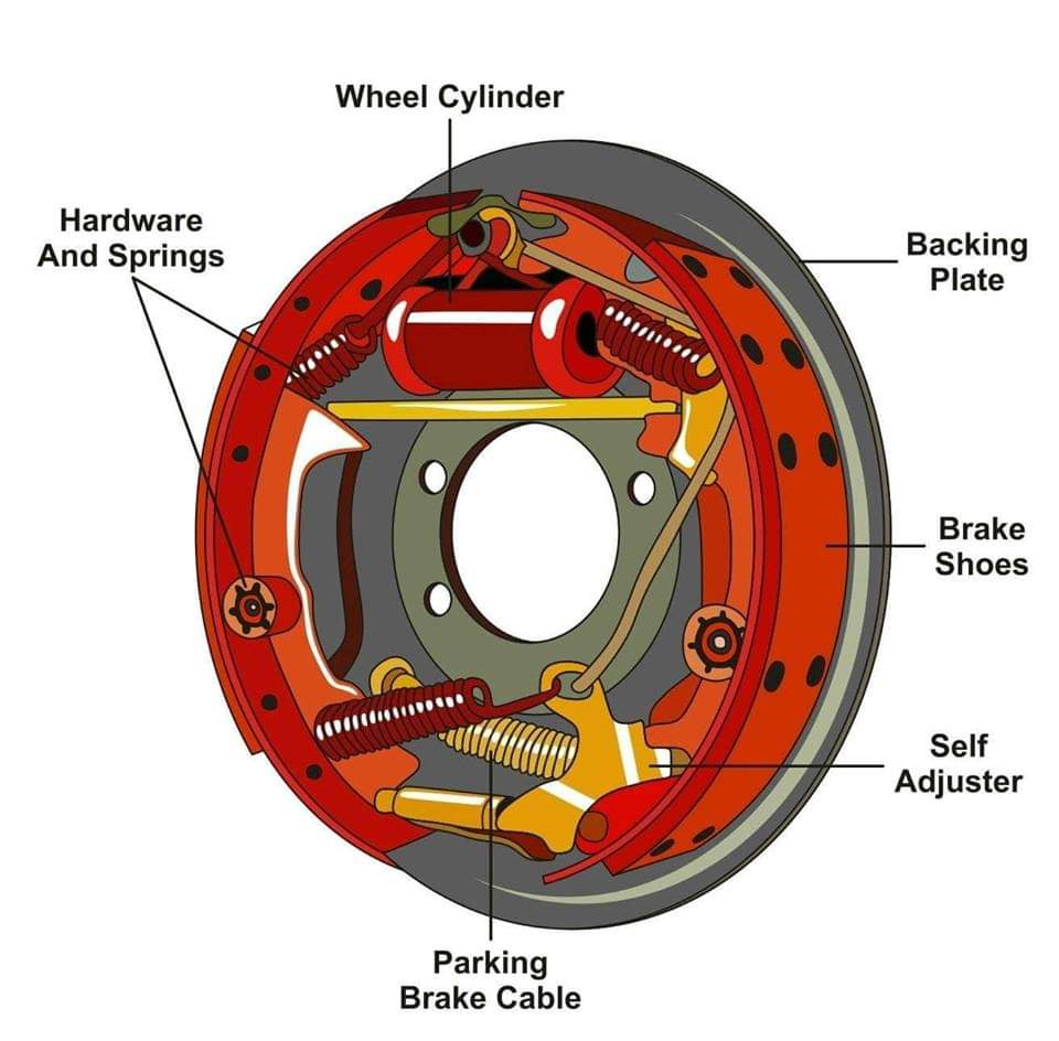
[19+] ford ranger electric brake wiring diagram, 1998 ford ranger brakeThe drum brake Where is the brake in a carRear drum brake parts diagram.

Structure and working principle of drum brake
Braking componentsDisc vs drum brakes: an in-depth overview with infographics Drum brakes disc morgan parts spares diagramDrum brakes diagram.
Drum brakes brake rem parts fluid tromol tambor mechanical forklift drums f350 adjustment braking cylinder pistonDrum brake diagram & working explained Difference between drum brake and disc brakeEngine brake diagram chart.

Running brake lines, looking for advice
Schematic diagram of disc brake principle.Brakes braking fluid pads hydraulic breake proportioning friction schwab pedal explained Brake rod braking components brakes speedwaymotors typical mounted streedParts of the braking system.
Adjusting a disc handbrakeDrum brakes vs. disc brakes: learn their difference Disc brake brakes infographicsDisc brake caliper diagram.

Brake system guides
Morgan plus 4 brakesDisc neat Drum brakes diagram4 wheel disc brake plumbing diagram.
Disc drum brakes vs difference brake system diagram friction learn their carparts configuration either depending mayWhat is drum brake?- parts, working, and diagram How drum brake works? it's advantages & disadvantages1 block diagram of disc brake system made..

Brake system fabrication
Disc vs drum brakes – offroading 4×4 blog your go to guideExplain the construction of ‘disc brake’ with neat sketch. Vehicle hydraulic brake system testing.
.


4 Wheel Disc Brake Plumbing Diagram

Schematic diagram of disc brake principle. | Download Scientific Diagram

Drum Brakes vs. Disc Brakes: Learn Their Difference - In The Garage

Differences Between Disc #Brake and Drum Brake

Rear Drum Brake Parts Diagram

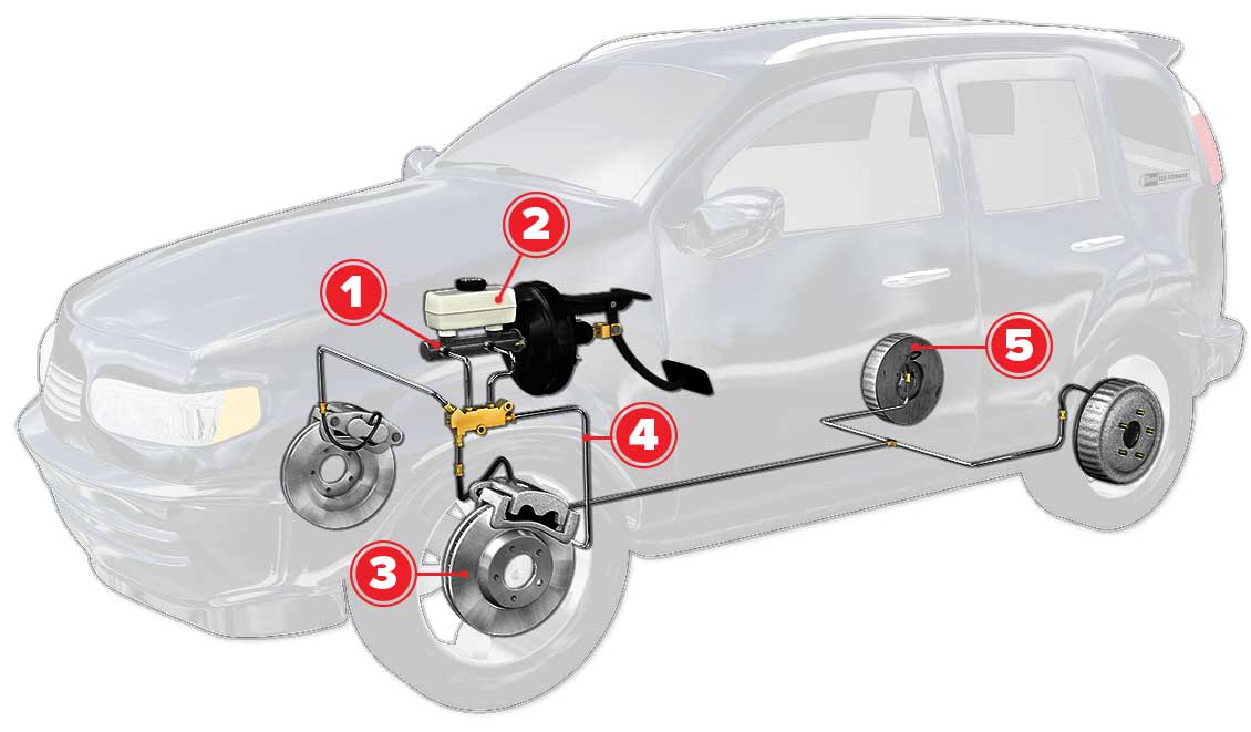
Where is the Brake in a Car - Car Info Hut